
Different Types of 5-Axis Machine Configurations
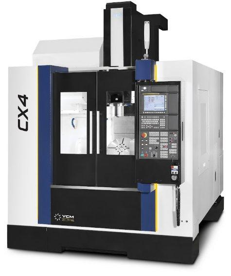
Machining a complex part can feel like solving a puzzle. Every angled surface or hard-to-reach feature changes how a cutting tool must approach the work. A 5-axis machining center gives shops more freedom to reach those features while keeping the part in one setup. Still, two machines with five axes can handle the same job very differently.
The difference often comes down to which components rotate. One design tilts the workpiece, while another swivels the spindle. A third shares rotary motion. Understanding these layouts helps buyers match equipment to their parts and production goals. Keep reading to explore the different types of 5-axis machine configurations.
How 5-Axis Machines Work
Every 5-axis milling machine uses three linear axes, X, Y, and Z. Those axes control straight-line movement through the machining envelope. Two additional rotary axes change the angle between the cutting tool and the workpiece, opening access to surfaces that might otherwise require another setup. Fewer setups reduce handling and can protect relationships between features.
Rotary-axis letters indicate the direction of rotation. The A-axis rotates around X, while the B-axis rotates around Y. The C-axis rotates around Z. However, those labels alone don’t tell you whether the spindle or the worktable performs the movement. The machine’s configuration provides that answer.
Table-Table Machines
In a table-table configuration, both rotary axes sit on the workpiece side. A tilting trunnion often supports a rotary table, which turns the part while the spindle keeps a fixed rotational orientation. The spindle moves linearly without swiveling.
Imagine machining a small aluminum housing with angled ports. The table can rotate and tilt the housing to present different surfaces to the cutting tool without anyone removing the part from its fixture. Operators familiar with vertical milling can easily visualize the workpiece movement.
Trunnion designs suit many small or midsize components, although their practical limits depend on the model. Part weight and overall dimensions affect clearance as the table tilts. A part may fit on the platter yet collide with the spindle at certain angles. Buyers should compare the full range of motion with their fixture dimensions, not just the advertised table diameter.
Head-Table Machines
A head-table configuration splits rotary motion between the spindle and the workpiece. Typically, the head tilts around one axis while the table rotates around another. Since the table doesn’t have to tilt the entire part, the layout can accommodate larger or heavier workpieces than many compact trunnion systems.
Consider a sizable steel component with features around its perimeter. The table turns the component while the spindle tilts to reach angled faces. A spacious table may accommodate multiple smaller parts when clearance permits.
Head-table machines have their own clearance considerations. The swiveling spindle assembly occupies space as its angle changes, and the cutting tool must avoid nearby clamps. Checking the head’s tilt range and the spindle’s reach helps buyers understand which features the machine can access without interference.
Head-Head Machines
In a head-head configuration, both rotary axes operate in the spindle assembly. The worktable doesn’t need to tilt or rotate for 5-axis cutting. Consequently, the machine can support large, heavy components on a stable platform while the tool changes orientation around them.
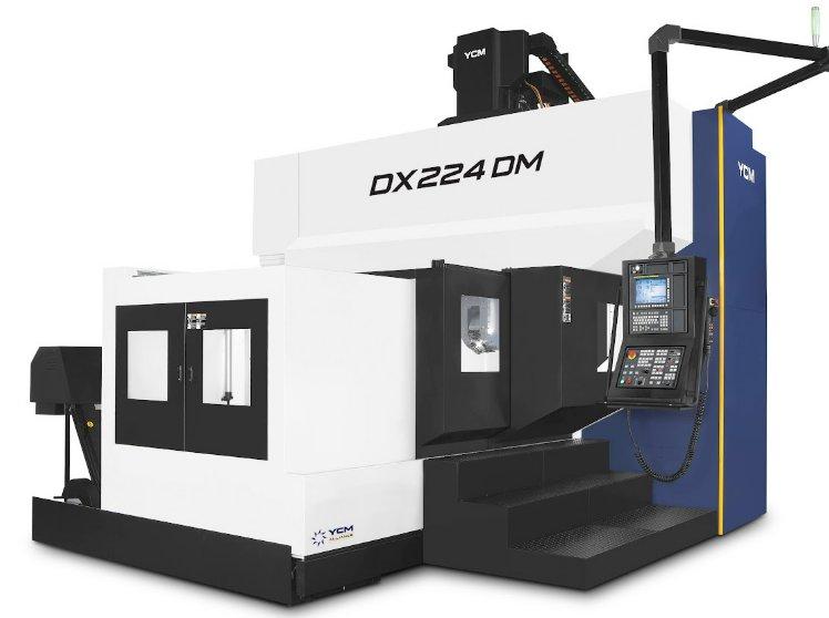
Manufacturers often choose this approach for large molds or aerospace structures that would place substantial loads on a moving trunnion. Some gantry and double-column machines use swiveling heads to reach complex surfaces across a broad work area. Head size and rotation limits still affect the cutting envelope.
Head-head equipment also demands careful programming. As the head pivots, the CNC control coordinates linear movement to keep the tool tip on the intended path. Tool length affects that motion, making calibration especially important.
Indexed or Simultaneous Cutting
Physical configuration tells you where the axes sit. Machining strategy tells you how the machine uses them. With indexed 5-axis machining, often called 3+2, the rotary axes position the workpiece or tool at a selected angle. The machine then cuts along its three linear axes while the rotary axes hold their positions.
3+2 machining works well for angled holes or separate flat features. Shops can machine multiple sides of a housing without reclamping, even when the tool doesn’t continuously change orientation during a cut.
Simultaneous 5-axis machining coordinates linear and rotary motion throughout the cutting path. The technique helps the tool follow contoured surfaces, such as turbine blade profiles, while maintaining a suitable cutting angle. Any of the three layouts can support simultaneous cutting with suitable controls and mechanics. Buyers should verify a model’s actual functions.
Vertical and Horizontal Layouts
Spindle orientation adds another consideration. Vertical machining centers approach the workpiece from above, which can make setup familiar to shops that already run conventional vertical mills. Horizontal machines approach from the side and may help chips fall away from certain cutting areas.
Neither spindle orientation dictates where the rotary axes belong. A vertical machine may use a trunnion table, while a horizontal machine can also incorporate tilting workholding. Gantry and double-column terms describe structural support. They don’t represent separate categories of rotary-axis placement.
YCM Machining Options
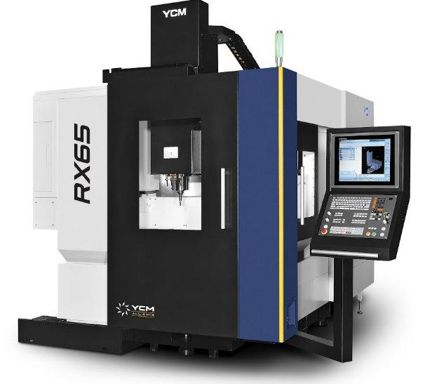
For buyers exploring 5-axis high-spec vertical machining centers, structural design deserves attention alongside rotary-axis placement. YCM Alliance offers several machine series within this category. The CF/CX series uses a rigid C-frame structure, while the RF/RX series uses a ram-type structure. Both designs emphasize machining stability and consistent precision.
The YCM RX65+ illustrates a trunnion-based approach. Its direct-drive trunnion table works with an 18,000-rpm spindle to support complex milling while limiting the need for additional setups. However, a model’s spindle speed alone can’t determine whether it suits an application. Buyers must evaluate the working envelope and part requirements.
What Buyers Should Check
Start with the largest part your shop expects to machine. Account for the fixture and the extra height that clamping adds. On a tilting table, the entire assembly sweeps through space, so the published linear travels won’t reveal every possible interference point.
Next, look closely at your cutting requirements. A machine that handles light finishing efficiently may need different spindle torque or structural rigidity for aggressive cutting in steel. Rotary-axis drive design and clamping capacity also affect stability under changing loads. For shops that frequently switch jobs, setup accessibility can have a meaningful effect on daily output.
Ask suppliers to evaluate a representative part. Review potential clearance issues and verify whether the controller supports your planned 3+2 or simultaneous operations. Productivity comparisons should cover tool changes and setup time along with cutting speed. Purchase price has a place in the discussion, but reliability and service support help protect productive machine hours over time.
Choose the Right Fit
You need to learn the different 5-axis machine configurations because not every layout wins every job. Table-table machines often make sense for compact workpieces that need access from several angles. Head-table designs can offer flexibility with larger parts, while head-head machines suit applications where moving the workpiece creates significant limitations.
Begin with the geometry your shop needs to cut, then consider the weight capacity and usable working envelope. At YCM Alliance, we can help buyers compare machining solutions around those requirements and their production goals. Choosing a configuration that supports today’s work and future projects can help protect part quality while keeping equipment productive.